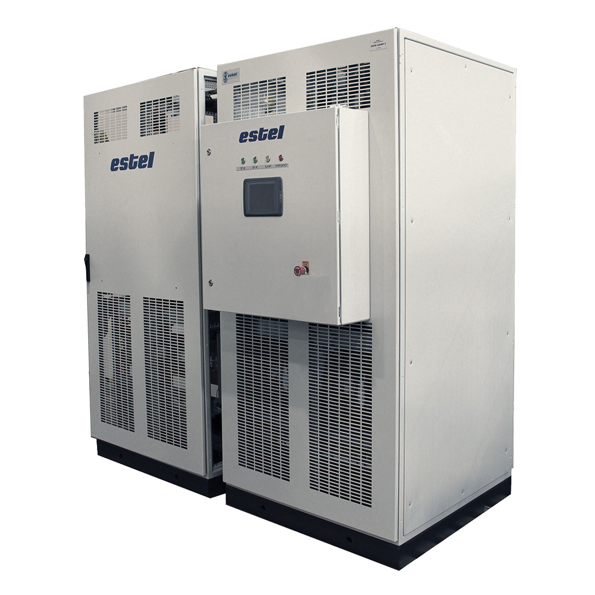
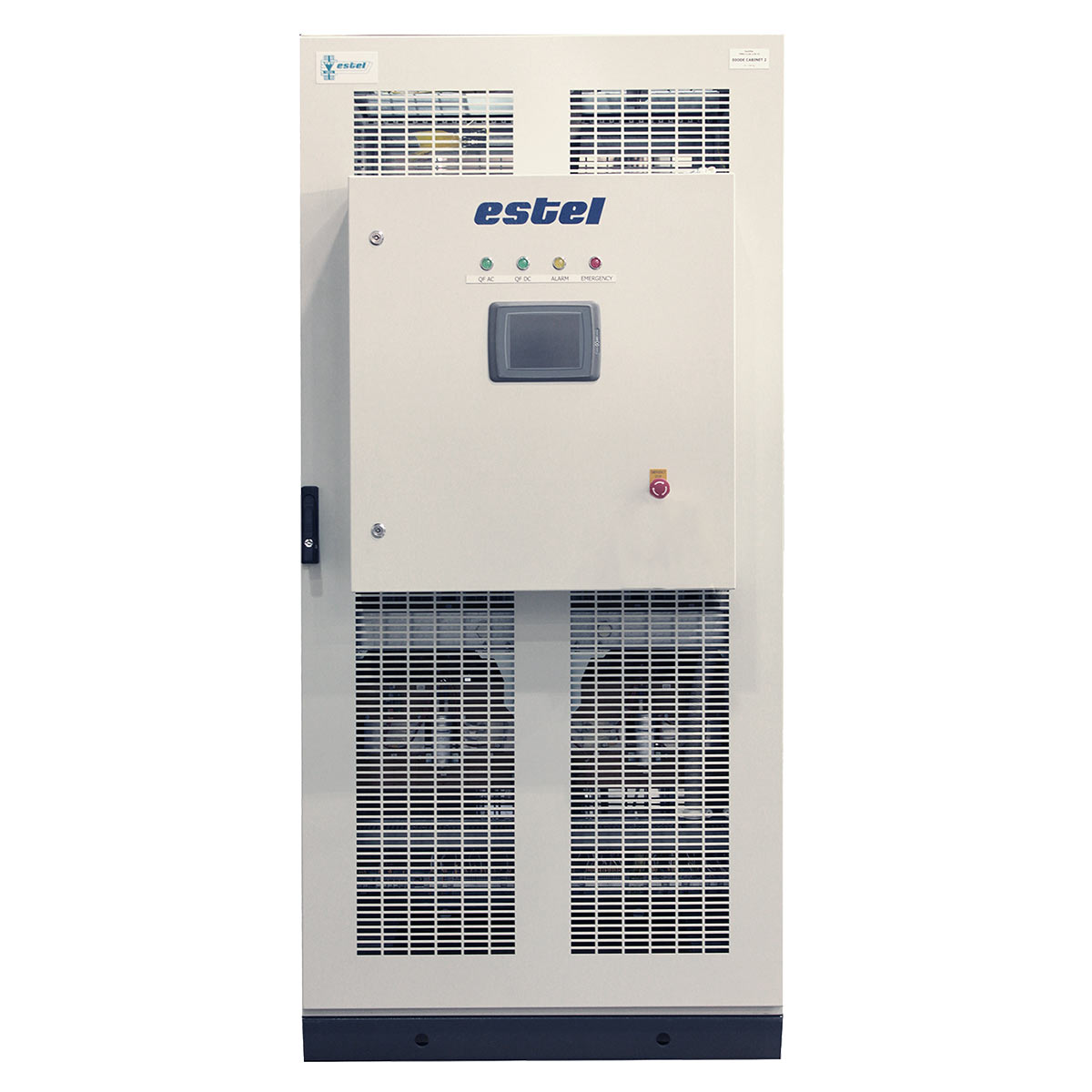
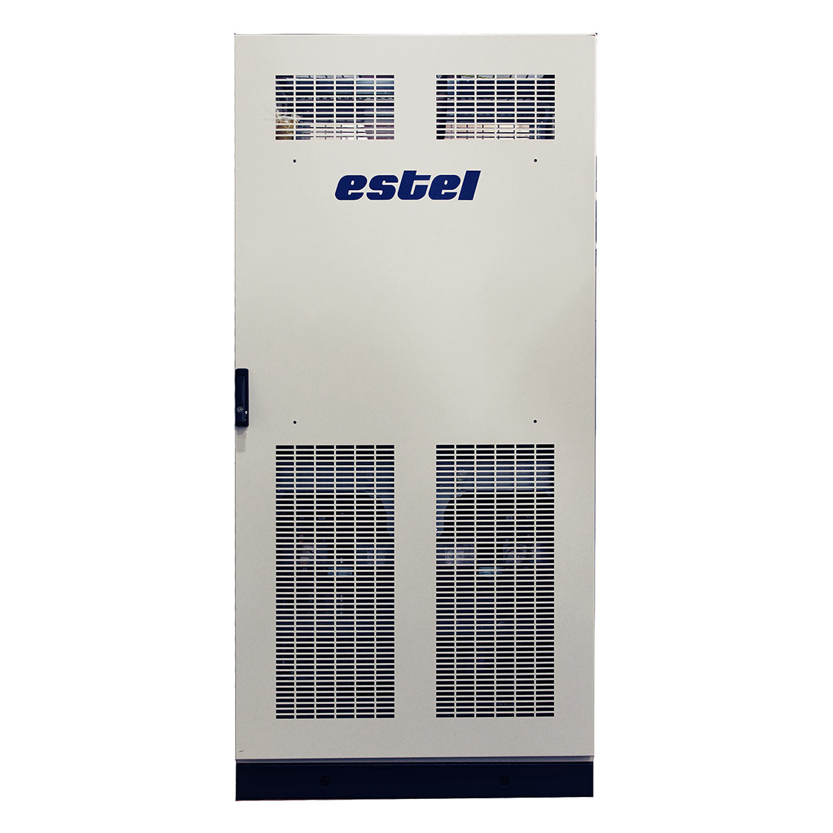
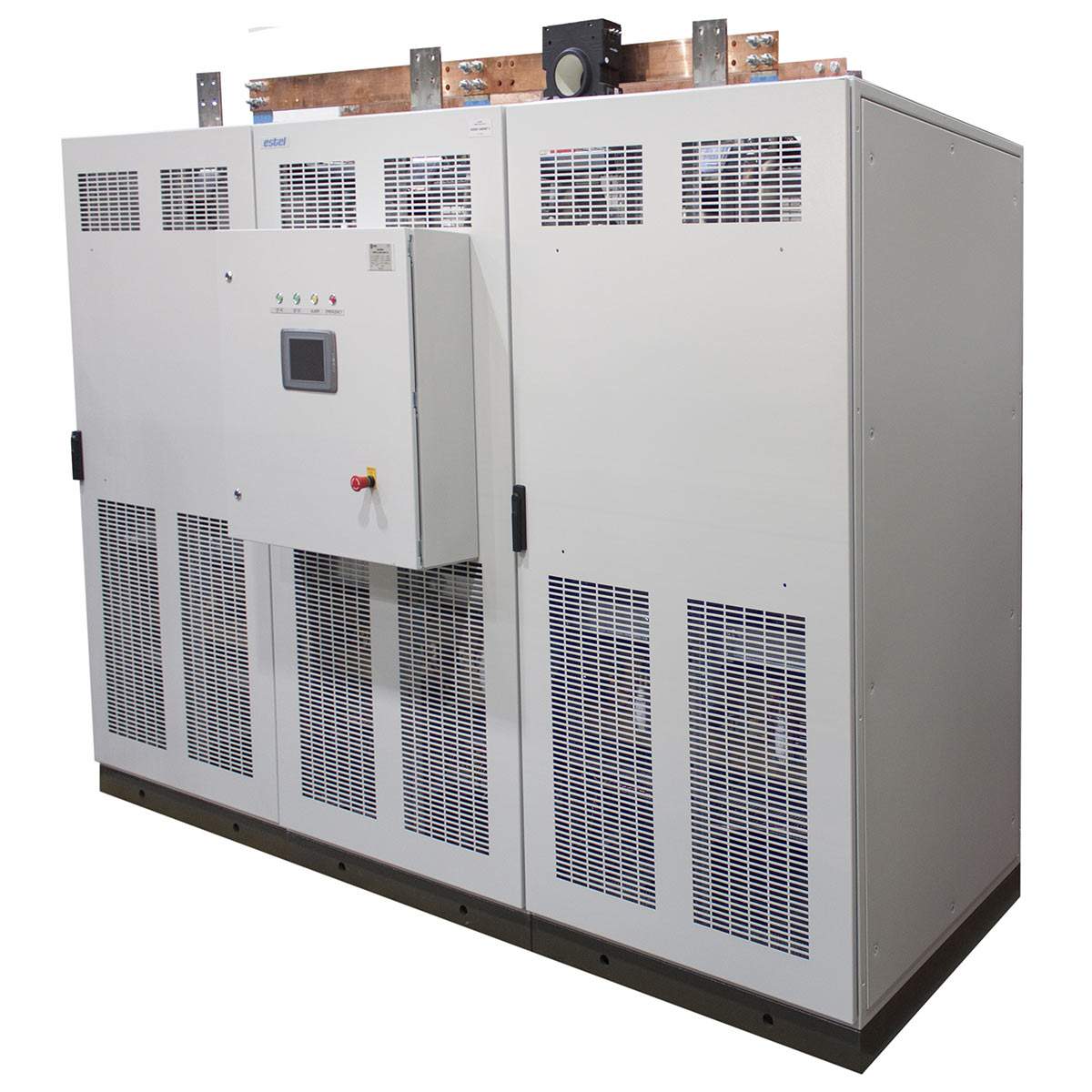
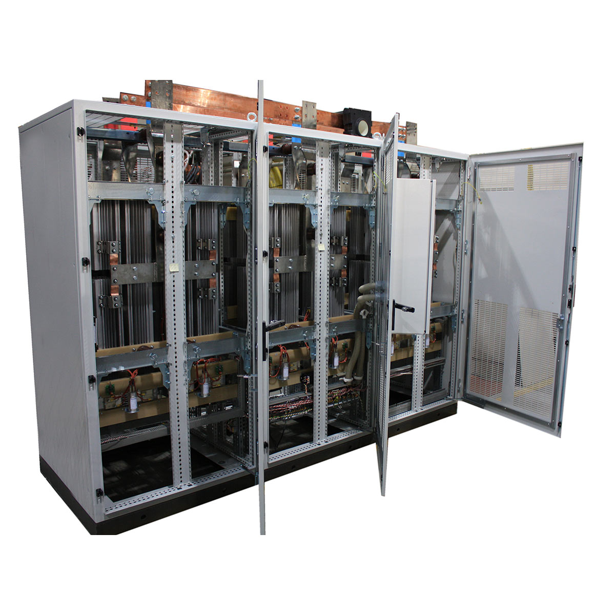
Rectifiers series V-MPED for traction substations of railway transport
The rectifier is designed to convert alternating current into direct current at DC traction substations of mainline railways.
Main benefits:
- Use of chillers with natural cooling ensures high reliability and overload capacity, maintenance is not required in the course of operation.
- Application of the diode blocks with a common chiller for two parallel diodes reduces quantity of buses and transitional contacts and as a result, reduces the losses.
- Application of thoriated clamp mechanism to create the required clamping force and special diode clamps allow quick replacement of diodes in place, without removing the power equipment and without the use of special measuring tools.
Design features:
In standard execution the rectifier is assembled according to 12-pulse current rectification circuit formed by subsequent connection of two bridges. The rectifier can be also assembled according to 6-pulse rectifier circuit.
Each diode is provided with the conductivity diagnostic circuit.
The rectifier is fitted with microprocessor protection and diagnostic system based on the controller manufactured by ESTEL Company, and is equipped with operator’s control panel provided with LCD display.
The microprocessor system is realized through the inner oscilloscope that allows to perform continuous monitoring of the following parameters: current, voltage, diodes conductivity, temperature at operation of the converting unit, and also to receive waveforms of the alarm signals, if they occur.
Designed to comply with RoHS and REACH requirements.
Operating conditions:
| Upper maximum value of the ambient temperature, °С | +45 |
| Lower maximum value of the ambient temperature, °С | -25 |
| Upper value of the relative air humidity at +25°С, % | 98 |
| Altitude above sea level, m | 2000 |
| Output parameters | |
| Rated active power, kW | 10400 |
| Rated voltage, V | 3300 |
| Rated current, А | 3150 |
| Overload current relative to rated value and time of the allowable overloads, s | 125 %– 900 sec, 1 time per 2 hours*
150 %– 120 sec, 1 time per 1 hour* 200 % – 10 sec, 1 time per 2 min** * root mean-square value for every 8 hours should not exceed rated current value ** root mean-square value for every 30 minutes should not exceed rated current value |
| Input parameters | |
| Rated voltage, V | 1305 |
| Rated frequency of the power supply voltage, Hz | 50 |
| Quantity of phases of power supply voltage | 2 х 3 |
| Rated current, А | 2571 |
| Voltage of the auxiliary power supply (50 Hz frequency), V | 220 |
| Cooling | air, natural |
| Power factor (design), minimum | 0,95 |
| Coefficient of performance (design), minimum | 0,98 |
| Ingress protection of: — power circuit — control system |
IP20 IP54 |
| Dimensions (W x H x D), mm | 3000 х 2300 х 1275 |
| Weight, maximum, kg | 2300 |
Portfolio
Any questions?
Contact us, we will be happy to answer!
Our clients


